Well Pump Control Box Wiring Diagram

Well Pump Control Box Wiring Diagram insidespaces howtopages wiring waterpump wiring waterpump Wiring a Water Well Pump Controller and Switch To wire up a pump in a water well is a relatively small project you can do yourself assuming Pump controller box Well Pump Control Box Wiring Diagram to test a well pump control boxTechnicians should test a well pump s control box before pulling a How to Test a Well Pump Control Box Inspect the control box s wiring diagram located on
electricalonline4u Controlling Single Phase MotorsSingle phase 3 wire submersible pump control box wiring diagram or single phase submersible pump starter wiring diagram and wiring installation guide Well Pump Control Box Wiring Diagram 483872A control box is used with a 3 wire pump the control box contains seeing a wiring diagram for the motor or the control well with a control box aermotor pdf PN280 pdf4 SUBMERSIBLE PUMPS Two and Three Wire for example No 8 8 4mm2 wire between pump and control box Figures 1 and 2 for installation wiring diagrams for
diychatroom Home Improvement PlumbingNov 21 2007 Deep Well Wiring Control Box and Pressure Switch User Name Remember Me How should it be set up for this type of pump Below is a diagram of the current set up Well Pump Control Box Wiring Diagram aermotor pdf PN280 pdf4 SUBMERSIBLE PUMPS Two and Three Wire for example No 8 8 4mm2 wire between pump and control box Figures 1 and 2 for installation wiring diagrams for to view on Bing5 53Aug 21 2014 2014 08 21 Well Pump Control Box Lance Knoechel Well Pump Installation and Wiring Single Phase Submersible Motor Starter Wiring Diagram Author Lance KnoechelViews 12K
Well Pump Control Box Wiring Diagram Gallery

Luxury Well Pump Control Box Wiring Diagram 31 In Msd 6A Wiring Diagram with Well Pump Control Box Wiring Diagram, image source: www.elvenlabs.com

Beautiful Well Pump Control Box Wiring Diagram 23 With Additional Tekonsha Brake Controller Wiring Diagram with Well Pump Control Box Wiring Diagram, image source: www.elvenlabs.com
3 wire submersible pump wiring diagram deep well submersible water pump wiring smartly printable wiring, image source: eidetec.com

3 wire pump diagram submersible well wiring best of 4, image source: agnitum.me

28 litre dual max 7, image source: www.diaoyurcom.com

goulds submersible pump wiring diagram emerson spl15fl2s wiring jpgresize6652c425 wiring diagram, image source: efcaviation.com

keelc gif, image source: ebooksnovedades.com


how to replace a water pump pressure switch wiring diagram water pressure control switch showing the electrical contacts well pump pressure switch wiring diagram, image source: www.replicasuper.com

Ignition input 1995 honda accord wiring diagram signal primary engine speed output battery ground control assembly, image source: www.easyhomeview.com
great wiring diagram for 1996 harley davidson fxr harley davidson of harley davidson sportster wiring diagram, image source: 4thdimension.org

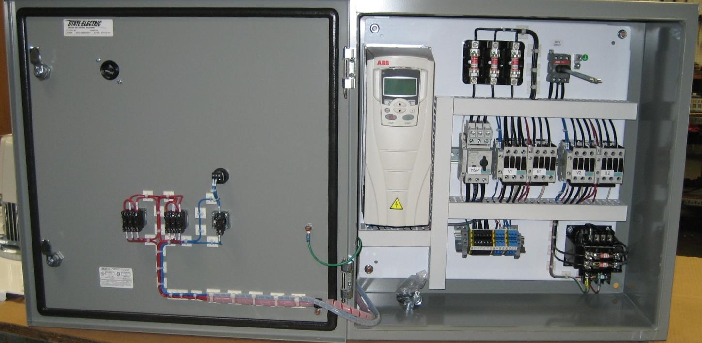
178, image source: motorsandcontrol.com

2010 07 26_233453_injector, image source: www.justanswer.com

manual at west coast classic cougar specializing in 1967 1968 throughout 1967 ford mustang parts diagram, image source: 4thdimension.org
model 1583_specs, image source: imageresizertool.com

tps lighting surge, image source: techomebuilder.com

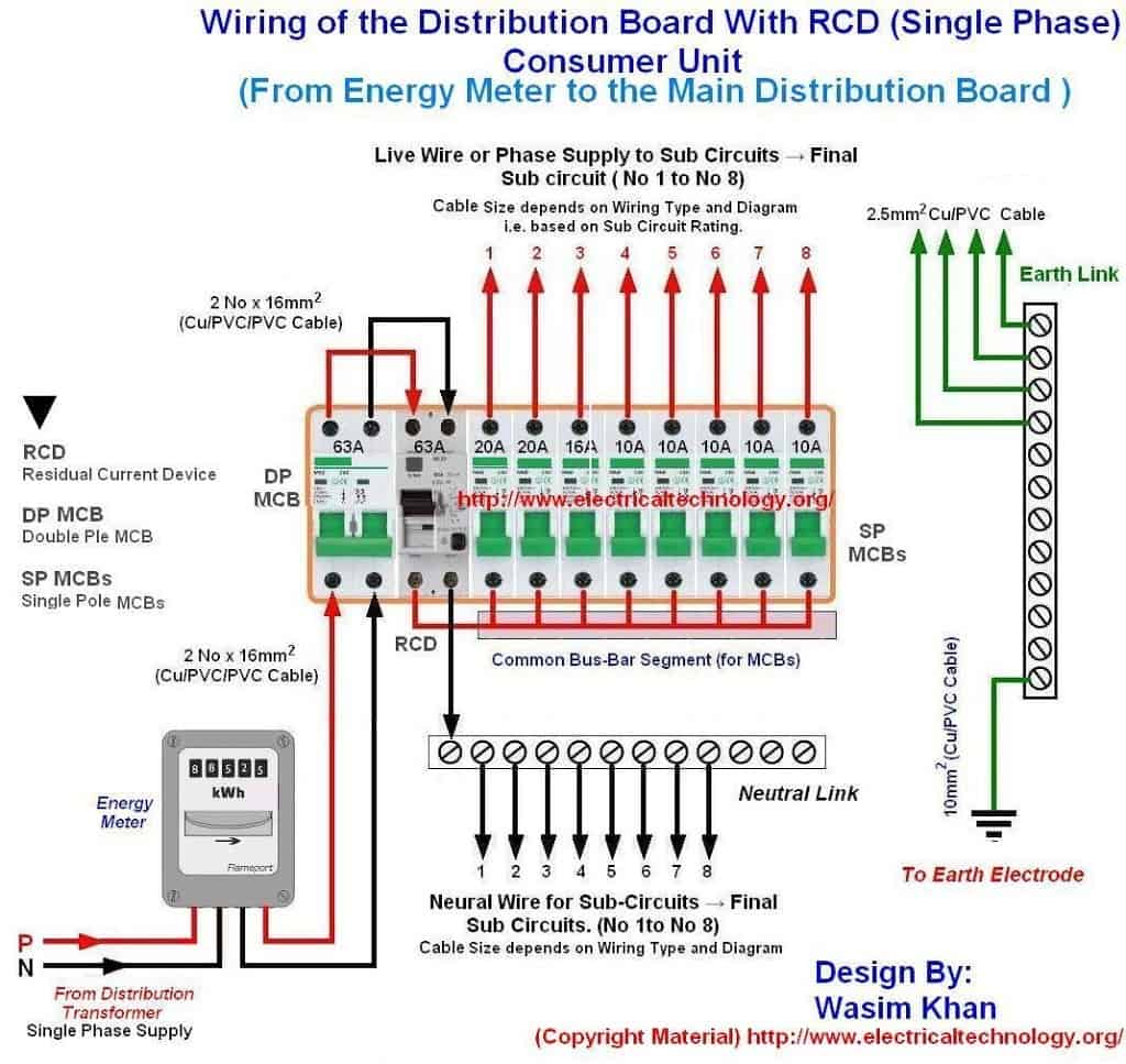
Wiring of the distribution board with RCD Single phase from Energy meter to the main distribution board 1024x967, image source: www.electricaltechnology.org
80 r129diagram_26c222a899ce81dff7c7197111f113642387fbb6, image source: mbworld.org

infgenerator transfer switch_clip_image002, image source: www.naturalhandyman.com


Comments
Post a Comment