Rtd Wiring Diagram

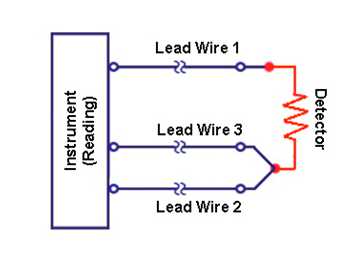
Rtd Wiring Diagram thermocouplertd contacts html2 Wire RTD Wiring Diagram Shown is a 2 wire RTD connected to a typical Wheatstone bridge circuit Es is the supply voltage Eo is the output voltage R1 R2 and R3 are fixed resistors and RT is the RTD In this uncompensatedcircuit lead resistance L1 and L2 add directly to RT Read more Rtd Wiring Diagram thermocouplertd 3 wire rtd html3 Wire RTD Wiring Diagram In this circuit there are three leads coming from the RTD instead of two L1 and L3 carry the measuring current
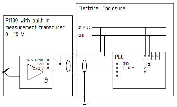
sierrainstruments products userfiles file manuals RTD RTD Wiring Instruments From IM 205 Rev F Appendix 3 September 2009 RTD Module and PT100 Wiring Module optional NOTE sensors and to the RTD module according to the following diagram on the left Note A1B1 A2B2 and C1C2 have the same wire Rtd Wiring Diagram scientific ezo rtd Wiringdiagram pdfEZO TM RTD Temperature Circuit Wiring diagram Revised 11 30 17 To connect an EZO TM Circuit to your microcontroller follow the diagram below Make sure the EZO TM Circuit and microcontroller share a common ground Isolation is not needed for the EZO TM RTD Temperature Circuit UART Mode Title ezo rtd Wiringdiagram Created Date pyromation Downloads Doc Training RTD Theory pdfRTD THEORY Page 3 2 wire construction is the least accurate of the 3 types since there is no way of eliminating the lead wire resistance from the sensor measurement 2 wire RTD s are mostly used with short lead wires or where close accuracy is not required
thermometricscorp 3 wire rtd htmlTweet 3 Wire RTD Description In order to minimize the effects of the lead resistances a three wire configuration can be used Using this method the two leads to the sensor are on adjoining arms Rtd Wiring Diagram pyromation Downloads Doc Training RTD Theory pdfRTD THEORY Page 3 2 wire construction is the least accurate of the 3 types since there is no way of eliminating the lead wire resistance from the sensor measurement 2 wire RTD s are mostly used with short lead wires or where close accuracy is not required gicthermodynamics PDF0808 RTD H pdf4 Configuration See Diagram RTD A 2 Wire Single Element D 4 Wire Dual Element B 3 Wire Single Element Std E 6 Wire Dual Element Resistance Temperature Detectors RTD Stainless Steel Sheath Typical 3 Wire Probe Construction Ceramic Encapsulated Element
Rtd Wiring Diagram Gallery
3 wire pt100 sensor wiring diagram and circuit schematic at to, image source: codecookbook.co

pt100 EMC wiring, image source: embdev.net

2678, image source: e2e.ti.com
Picture5, image source: www.sterlingsensors.co.uk
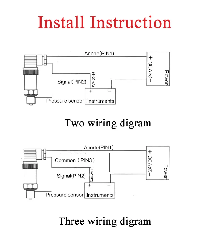
Transmitters 2 4 wires, image source: efcaviation.com

HTB1Yw7XKXXXXXXsXpXXq6xXFXXXS, image source: meacon.en.alibaba.com
CAN_application_01_large, image source: www.rtd.com

Interfacing EM 18 RFID Reader Module with PIC Microcontroller, image source: electrosome.com
2006 12 15_173254_ja1, image source: www.justanswer.com


f_rgkod dubbel pt100 w200, image source: pentronic.se
Legg_diagram2_06042012, image source: www.odicis.org

Pbox16 D_openview, image source: www.auberins.com

motorSectionBIG, image source: www-mdp.eng.cam.ac.uk


Thin_Film_PRT, image source: en.wikipedia.org
40371, image source: www.monoprice.com
s8K, image source: en-us.fluke.com


Comments
Post a Comment