Led Driver Wiring Diagram
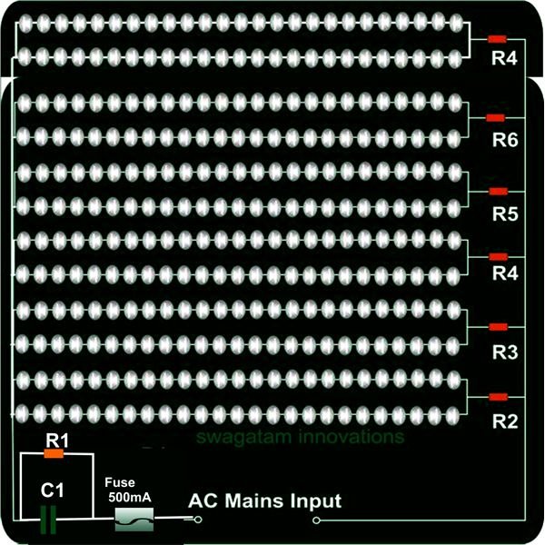
Led Driver Wiring Diagram led driver circuitThis is a simple 230v LED Driver circuit diagram which is used for home lightening systems and also can be used as an indicator Led Driver Wiring Diagram diagramsNeed a little help wiring or getting something connected check our Wiring Diagrams This is our standard wiring LED is rated for up to drivers together Apex
bodine downloads install BSL310 inst std 443529060961 pdfSTEP 3 WIRING THE EMERGENCY DRIVER Select the appropriate wiring diagram to connect the emergency driver to the AC driver and LED load Make sure all connections are in accordance with the National Electrical Code Led Driver Wiring Diagram usailighting 0 10v dimming0 10V dimming is the simplest control to the minimum light level allowed by the dimming driver 0 10V wiring diagram is shown below 0 10V Dimming images philips is content PhilipsConsumer PDFDownloads United Wiring Diagram Input Output and 0 2 8 LED Driver maximum allowable case temperature is 80 C via Class 2 wiring 3 6 When the drivers are installed in the
crenshawlighting wp content uploads LED wiring guides pdfCRENSHAW crensha wlighting com Crenshaw LED 0 10V dimming wiring diagram 0 10V dimmer switch Leviton IP710 LFZ or equal For other types of dimming Led Driver Wiring Diagram images philips is content PhilipsConsumer PDFDownloads United Wiring Diagram Input Output and 0 2 8 LED Driver maximum allowable case temperature is 80 C via Class 2 wiring 3 6 When the drivers are installed in the LED ELECTOC DVES 1 LED Drivers Xitanium LED Driver Wiring Diagrams 6 11 to 6 12 Visit our web site at philips advance
Led Driver Wiring Diagram Gallery

0 10v dimming wiring diagram, image source: fitfathers.me
doc tinkerforge example schematic with battery two switches and led_switches in a circuit_digital voltmeter voltage regulator design schematic electrical wire size 48 volt battery bank, image source: togelll.com

sch leds, image source: symlink.dk

dali lighting control system, image source: www.alibaba.com
dot matrix, image source: wiringdiagram.karaharmsphotography.com
ece spring adapative alarm clock one led decoder there are four total for each segment display_led 7 segment display circuit_555 timer circuit amplitude modulation using transistor sim, image source: farhek.com
TED4_web, image source: www.liteplan.com
O 10V+Dimming+Line+Voltage+Ballast+Ballast+NOTES%3A, image source: www.gsmx.co

8603b49a5c1b4ead09a993a9a6686c0f7b0a08b8_large, image source: www.brighthubengineering.com

424674237_579, image source: www.alibaba.com
Christmas_star001, image source: www.gadgetronicx.com

2009 2010 toyota corolla electrical wiring diagrams 4 638, image source: www.slideshare.net
ZK60L, image source: electronics.stackexchange.com
stp16, image source: www.hownottoengineer.com

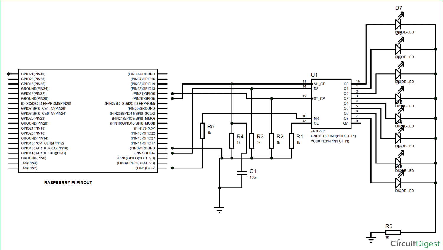
Raspberry Pi with Shift Register circuit diagram, image source: circuitdigest.com

120v wiring, image source: www.topbulb.com

maxresdefault, image source: www.youtube.com

Visitor monitoring with raspberry pi camera circuit diagram, image source: circuitdigest.com
file_62329_xbox one controller front large, image source: estrategys.co
TB6560 3A Stepper Motor Driver Board Single Axis 02, image source: www.electrodragon.com
Comments
Post a Comment