Capacitor Wiring Diagram
Capacitor Wiring Diagram reference Home Maintenance ElectricalWiring a capacitor to start a motor begins with the connection of the positive terminal of the motor to the resistor Take one terminal of the resistor and connect it to the capacitor Read the wiring diagram on your appliance to understand the colors that the manufacturer designed for the three Capacitor Wiring Diagram brighthubengineering DIY Digital Analog ElectronicsWondering how a capacitor can be used to start a single phase motor Click here to view a capacitor start motor circuit diagram for starting a single phase motor
hvachowto 2014 11 12 start run capacitor93 thoughts on Start and Run Capacitor Explained Ray Lewis July 27 2018 The wiring diagram said to hook it up to the common lead on the capacitor Capacitor Wiring Diagram to view on Bing9 05Dec 29 2013 HVAC Shop Talk podcast represents the blue collar boys and girls in the skilled trades especially HVAC In this video Zack Psioda explains how many dual ru Author HVAC Shop Talk PodcastViews 361K dms hvacpartners docs 1009 Public 01 WD561C 18 6 pdffactory power wiring connection diagram schematic diagram ladder form cap capacitor dual run wiring diagrams 1 and 3 phase 60 hertz
wire capacitor motor blowers The above illustration does not cover every single type of motor wiring available on the market However motor and capacitor diagram represents a vast majority of motors and capacitor wiring available to the general public Capacitor Wiring Diagram dms hvacpartners docs 1009 Public 01 WD561C 18 6 pdffactory power wiring connection diagram schematic diagram ladder form cap capacitor dual run wiring diagrams 1 and 3 phase 60 hertz caraudiohelp car audio capacitor installation htmlThere is often a lot of confusion on how to wire a car audio capacitor In the diagram both capacitors have their ground terminals wired together but you could
Capacitor Wiring Diagram Gallery

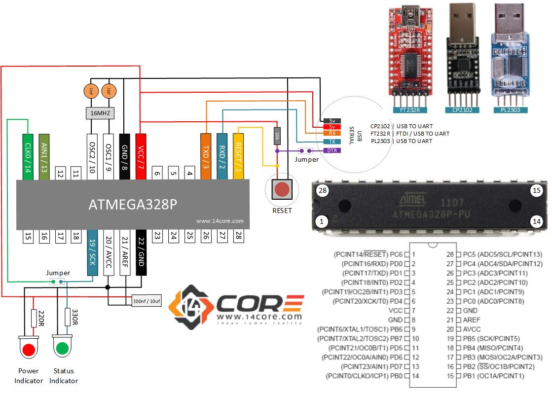
ATMEL ATMEGA328P stand alone wiring diagram schematic guide 14core, image source: www.14core.com
beautiful 2wire gm alternator wiring diagram ideas electrical of bosch alternator wiring diagram, image source: asfbconference2016.org

can i use existing wireing for ny new garage door opener i was able to get the manual and ill give you a cut for the wiring garage door opener wiring diagram, image source: www.teeflii.com

leds_Wiring Diagram, image source: forum.arduino.cc

30086933 b2c78d50 9295 11e7 8404 497d65b66bc0, image source: github.com
component logic circuit design digital probe for electronics part ivb vending machine example free pdf thumbnail_and gate cmos circuit_circuits book dark detecting led circuit fm, image source: farhek.com
ABB simplified diagram, image source: www.windpowerengineering.com

60 W Switching power supply, image source: powersupply33.com

Fluorescent_lamp_classic_power_circuit, image source: commons.wikimedia.org
image07, image source: www.waltech.com
using android to control arduino via bluetooth hc module image_arduino to android_circuit diagram physics why are resistors used in boards voltage a series parallel the schematic electro, image source: farhek.com
transformers wallpapers autobots wallpaper cave hd pictures_definition of transformer_12 volt 5 pin relay diagram clipping circuit resistor color code test complex arduino projects, image source: farhek.com
component symbol of thermistor electrical aqa igcse certificate physics 1e circuit symbols at wakefield_electrical circuit symbols_switch mode power supply circuit countdown, image source: farhek.com

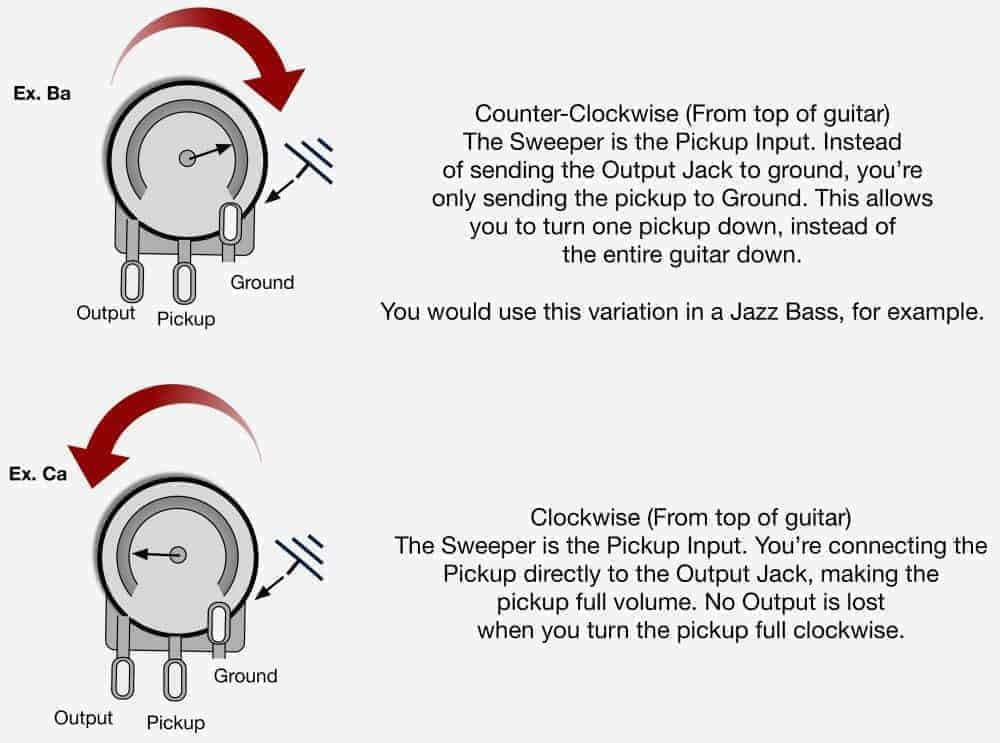
Push Pull Pots Article 1000x743, image source: www.fralinpickups.com

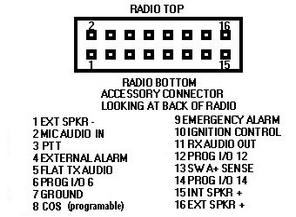
Connector_pins_En, image source: support.smartptt.com
Bluesbreaker1, image source: www.tonegeek.com
electric circuits on emaze a circuit is way of routing electricity along path_about electricity and circuits_centrifugal switch in single phase induction motor electronic component, image source: farhek.com
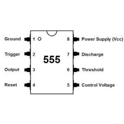
lm555 timer ic timer ic list rm0066 by robomart a16239 500x500, image source: www.robomart.com
mesa road king showing power transformer, image source: tonymckenzie.com

Comments
Post a Comment