Can Bus Wiring Diagram
Can Bus Wiring Diagram interfacebus can bus io schematic diagram htmlCAN Bus equivalent Output Circuit Typical output voltages are 2 4v Voh and 0 4v Vol for the receiver R While the CANH line can range up to 7 volts and the CANl line line Can Bus Wiring Diagram CAN Bus is an automotive bus developed by Robert Bosch which has quickly gained acceptance into the automotive and aerospace industries CAN is a serial bus protocol to connect individual systems and sensors as an alternative to
tekeye uk automotive can bus cable wiringCAN Bus Wiring Diagram a Basics Tutorial The CAN bus is a common digital network used in automotive industrial medical and scientific systems for routing sensor data between pieces of equipment The main advantages are high resilience to noise reliability low cost simple wiring and ease of use Can Bus Wiring Diagram xenondepot HID kit wiring can bus DRL explained s 41 htmHome Buyer s Guide HID Kit Wiring CAN BUS And DRL Explained HID Kit Wiring CAN BUS And DRL Explained The wiring and electrical system in a vehicle are designed and configured to operate the equipment originally installed by the automaker consulab files canBusHandout pdfThe diagram has lines across the CAN Bus indicating that the Bus is a twisted pair of wires The twisting of the wires helps to prevent interference The ConsuLab MP 1918 is a state of art trainer that simulates a vehicle CAN Bus system The diagram of the CAN Bus system looks like this Notice that the CAN Bus has two wires green and yellow
pransystems resource center can bus j1939 wiring standardthis page contain diagram for CAN bus J1939 standard connection for PRAN s electronic modules Can Bus Wiring Diagram consulab files canBusHandout pdfThe diagram has lines across the CAN Bus indicating that the Bus is a twisted pair of wires The twisting of the wires helps to prevent interference The ConsuLab MP 1918 is a state of art trainer that simulates a vehicle CAN Bus system The diagram of the CAN Bus system looks like this Notice that the CAN Bus has two wires green and yellow interfacebus Can Bus Connector Pinout htmlCAN bus pinout and CANopen pinout including Signal names and pin description
Can Bus Wiring Diagram Gallery

vintagebus vw bus wiring diagrams bug 1956 cadillac diagram, image source: norwalkkiwanis.org
Best Bus Bar Wiring Diagram 29 For 2002 Jetta Stereo Wiring Diagram with Bus Bar Wiring Diagram, image source: www.elvenlabs.com

main main automatic transfer scheme, image source: www.masaleh.co

24C256 EEPROM Wiring Diagram Schematics 001, image source: www.14core.com

attachment, image source: readingrat.net

Wiring+Diagram+Wiring+Diagram+DMX+bus+DMX+bus, image source: slideplayer.com

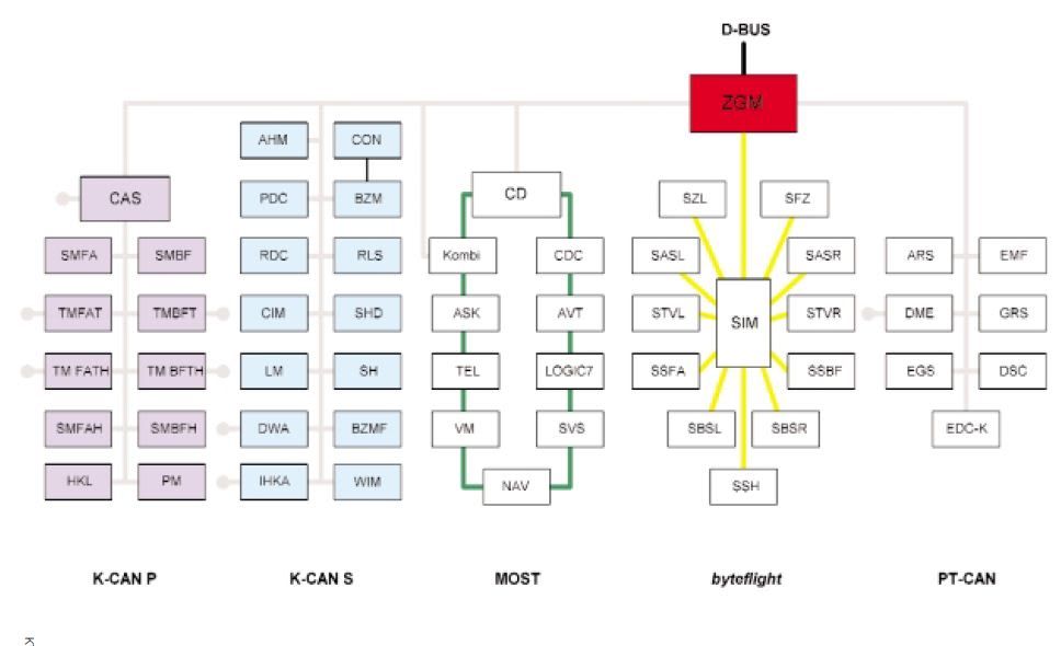
E65E66BusNetwork, image source: www.bimmerfest.com


applicationImage I 7532, image source: www.icpdas-usa.com
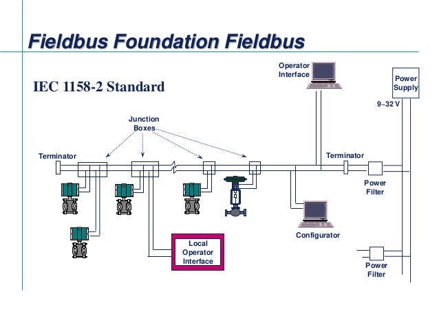
fieldbus tutorial part 4 installation of fieldbus 11 638, image source: www.slideshare.net
WIring DIagram DS32315N Real Time Clock Schematics Connection, image source: www.14core.com

Wiring SD Card Module Pinout Schematics diagram, image source: www.14core.com

diag_isobus_diagram, image source: www.deere.com

webinar abb building automation busch controltouch knx, image source: new.abb.com


maxresdefault, image source: www.youtube.com
280036356513268, image source: www.cnblogs.com

slider2 2015_premium_D, image source: www.jaeger-automotive.de


board side a, image source: www.chipworks.com
proxy, image source: forum.allaboutcircuits.com


ATCH 050498, image source: www.metz-connect.com
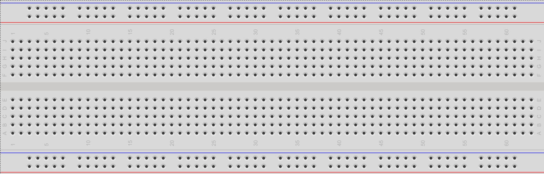
BreadBoard, image source: microcontrollerelectronics.com


Comments
Post a Comment