3 Wire Rtd Wiring Diagram
3 Wire Rtd Wiring Diagram thermocouplertd 3 wire rtd htmlWhy Use a 3 Wire RTD The three wire configuration provides a compensation loop that can be used to subtract the lead wire resistance 3 Wire RTD Wiring Diagram 3 Wire Rtd Wiring Diagram shopbangolufsen wiring wiring diagram for 3 wire rtdWiring diagram for 3 wire rtd furthermore wiper wiring 80 cj5 5867 together with 4 wire sensor wiring diagram together with cutler hammer gfci breaker wiring diagram also yamaha kodiak 450 wiring diagram further pt100 rtd blogspot in addition john deere stx38 wont start lawn mower forums lawnmower along with three phase motor wiring diagram
altahaddi 3 3 wire rtd wiring diagram3 wire rtd wiring diagram as well as platinum resistance thermometer as well as rosemount 3051s wiring diagram as well as polarity 3 wire rtd wiring diagram along with chapter 3 generator excitation and also showthread as well as what is a thermocouple further pickwickian syndrome history also en moreover elecsymbols 3 Wire Rtd Wiring Diagram thermometricscorp 3 wire rtd htmlIn a 3 RTD there are 3 leads coming from the RTD Sensor The effect of the lead wire resistance can be eliminated by using 3 wires of equal resistance 3 wire rtds are the most commonly used configuration readingrat Wiring diagram3 wire rtd wiring diagram wirdig at wiring diagram Wiring Diagram For 3 Wire Rtd One of many automotive repair projects that
4 wire rtd wiring diagramEliminating sensor errors in loop calibrations from cole parmer rosemount 3 wire rtd in wiring diagram 4 similiar rosemount 3 wire rtd wiring diagram keywords four wire rtd pyromation rtd wiring diagram 4 wire 3 Wire Rtd Wiring Diagram readingrat Wiring diagram3 wire rtd wiring diagram wirdig at wiring diagram Wiring Diagram For 3 Wire Rtd One of many automotive repair projects that instrumentationtools Temperature MeasurementDifference Between 2 wire RTD 3 wire RTD RTD Wiring Diagram 2 lead constructions result in leadwire resistance getting added to the element resistance
3 Wire Rtd Wiring Diagram Gallery

pt100 3 wire wiring diagram rtd and schematic throughout to, image source: wiringdiagram.karaharmsphotography.com
RTD PT100 to 4 20mA Converter Module RTD PT100 Temperature Transmitter PT100 to Current Converter Zero, image source: walremal.com


industrial thermocouple wiring diagram 320x453, image source: blog.lesman.com

Thermocouple Colour Code Chart jpg, image source: elsalvadorla.org

Thermocouple_circuit, image source: vesselyn.com
plc wiring diagram guide ohiorising org in, image source: agnitum.me

2, image source: www.radiolocman.com
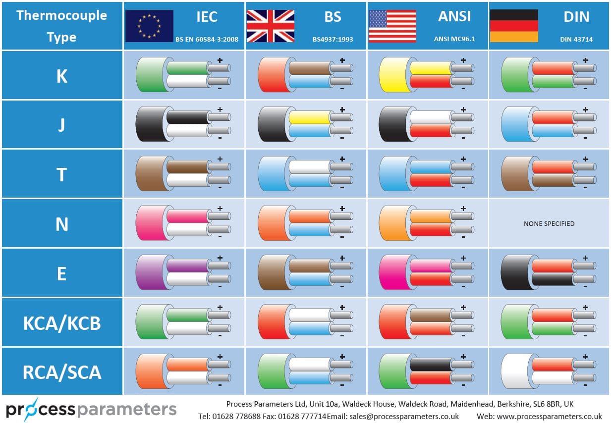
Thermocouple Colour Code Chart jpg, image source: www.processparameters.co.uk
ther1, image source: www.bristolwatch.com

Industrial%20Head%20Assembly%20Thermocouple%20Probe_2_Sale_1, image source: estrategys.co

MAX31865 sch, image source: hallard.me

sensor_80, image source: www.ni.com

201112614152959, image source: www.seekic.com

thermocouple_tolerance, image source: www.thermometricscorp.com

ref_pg1, image source: www.iprocessmart.com
ref_pg4, image source: www.iprocessmart.com


Comments
Post a Comment